_1745308399_WNo_1600d900.webp)
A lathe is a cornerstone machine tool in machining, designed to shape materials like metal, wood, or plastic by rotating a workpiece against a stationary cutting tool. The workpiece is secured on a spindle, which rotates at controlled speeds, allowing the cutting tool to remove material with precision to create cylindrical, conical, or other symmetrical shapes. Lathes are highly versatile, capable of performing operations such as turning, facing, drilling, boring, threading, and knurling. This flexibility makes them essential in industries ranging from automotive and aerospace to furniture and jewelry production, as well as in hobbyist workshops for crafting custom parts with high accuracy.
The lathe’s history stretches back to ancient Egypt around 1300 BCE, where bow lathes were used for rudimentary woodturning, powered by hand or foot. By the Middle Ages, pole lathes with pedal mechanisms improved efficiency and control, enabling more intricate work. The Industrial Revolution in the 18th century marked a turning point, introducing steam- and water-powered lathes that supported mass production. In the 20th century, electric motors enhanced reliability, and the development of computer numerical control (CNC) lathes revolutionized the industry by automating complex tasks. Today, modern lathes combine precision engineering and digital control, producing intricate components for advanced applications.
Lathes are categorized by their design and application, each suited to specific tasks. Engine lathes, the most common type, are versatile and widely used in small to medium workshops for general-purpose machining, offering manual control over a range of operations. Turret lathes feature a rotating tool turret that holds multiple cutting tools, enabling rapid tool changes for high-volume production. CNC lathes, controlled by computer programs, provide unmatched precision and automation, ideal for complex geometries in industries like aerospace and medical device manufacturing. Bench lathes, smaller and more compact, are designed for precision work on small workpieces, making them popular among hobbyists and in educational settings. Choosing the right lathe depends on factors like project scale, material, and required precision.
The headstock is the powerhouse of the lathe, located at the left end of the machine, and serves as the primary drive mechanism. It houses the spindle, which is driven by a motor through belts or gears, and rotates the workpiece at variable speeds. The headstock contains bearings to ensure smooth spindle rotation and often includes a gear system for speed adjustments. It also supports the chuck or other work-holding devices that secure the workpiece. A well-maintained headstock is critical for precision, as any misalignment or wear can affect the accuracy of the machined part.
The tailstock, positioned at the right end of the lathe, provides support for the opposite end of the workpiece, especially for long or slender pieces. It is mounted on the bed and can slide along it to accommodate different workpiece lengths, locking securely in place during operation. The tailstock houses a quill, which can extend or retract and typically holds tools like drill bits or a center (live or dead) to stabilize the workpiece. Proper tailstock alignment with the headstock is essential to prevent tapering or inaccuracies in machining.
The bed is the rigid foundation of the lathe, typically made of cast iron to withstand heavy loads and vibrations. It provides a flat, precisely machined surface on which the headstock, tailstock, and carriage are mounted. The bed’s ways—polished tracks or rails—ensure accurate movement of the carriage and tailstock. Its robust construction minimizes deflection under load, maintaining alignment and precision during machining. Regular cleaning and lubrication of the bed are vital to prevent wear and ensure smooth operation.
The carriage is a movable assembly that travels along the bed’s ways, carrying the cutting tool toward or away from the workpiece. It consists of several components, including the saddle, which rides on the bed, and the apron, which contains gears and controls for movement. The cross-slide, mounted on the saddle, allows the tool to move perpendicular to the workpiece, while the compound rest provides angular adjustments for precise cuts. The carriage’s smooth and controlled motion is crucial for achieving accurate dimensions and surface finishes.
The chuck and tool post are critical for securing the workpiece and cutting tool, respectively. The chuck, mounted on the headstock spindle, grips the workpiece and is typically a three-jaw (self-centering) or four-jaw (independent) type, chosen based on the workpiece’s shape and precision needs. The tool post, mounted on the carriage’s compound rest, holds the cutting tool securely and allows for quick tool changes or angle adjustments. Proper setup of the chuck and tool post ensures stability, safety, and precision during machining operations.

Wearing appropriate personal protective equipment (PPE) is critical when operating a lathe to minimize the risk of injury. At a minimum, operators should wear safety glasses or a face shield to protect against flying chips and debris, which can be propelled at high speeds during machining. Hearing protection, such as earplugs or earmuffs, is recommended for prolonged exposure to lathe noise. Close-fitting clothing and sturdy, non-slip work boots prevent entanglement with rotating parts, while gloves should be avoided near moving components to reduce the risk of being caught. Long hair must be tied back, and jewelry should be removed to ensure nothing interferes with safe operation.
Preparing the lathe work area is essential to ensure a safe and efficient machining environment. The area should be well-lit, clean, and free of clutter, such as tools, materials, or spilled lubricants, to prevent tripping or slipping hazards. Ensure the lathe is placed on a stable, level surface to avoid vibrations or tipping during operation. Keep flammable materials away from the lathe, as cutting fluids and metal chips can pose fire risks. Additionally, maintain clear access to the lathe’s controls and emergency stop mechanism, and use barriers or signs to restrict unauthorized access, especially in shared workshops.
The emergency stop mechanism is a critical safety feature on a lathe, designed to immediately halt all machine operations in case of a hazard. Typically a large, red, easily accessible button or switch, it is located on the lathe’s control panel or near the operator’s position. Before starting any operation, familiarize yourself with the location and function of the emergency stop and test it to ensure it works correctly. In an emergency, such as a tool jam, workpiece dislodgement, or operator error, pressing the emergency stop will cut power to the motor and stop the spindle, preventing potential injuries or damage. Regular maintenance of this mechanism is vital to ensure its reliability.

Before operating a lathe, a thorough inspection of the machine is essential to ensure safe and accurate performance. Begin by checking for visible signs of wear, damage, or loose components, such as bolts, belts, or gears, particularly in the headstock, carriage, and tailstock. Verify that the bed’s ways are clean and free of debris, as chips or dirt can affect movement and precision. Confirm that all lubrication points are adequately oiled according to the manufacturer’s specifications to reduce friction and wear. Test the spindle and carriage controls to ensure smooth operation, and check the emergency stop mechanism to confirm it functions correctly. Addressing any issues during inspection prevents accidents and ensures optimal machining results.
Properly mounting the workpiece is critical for safe and precise lathe operation. Depending on the workpiece’s shape and size, select an appropriate work-holding device, such as a three-jaw chuck for cylindrical parts or a four-jaw chuck for irregular shapes requiring precise centering. Secure the workpiece firmly in the chuck, ensuring it is seated evenly to avoid vibration or wobbling during rotation. For longer workpieces, use a center in the tailstock to provide additional support. Always double-check that the chuck jaws are tightened securely and that the workpiece is balanced to prevent it from coming loose at high speeds, which could damage the lathe or cause injury.
Aligning the tailstock with the headstock is vital for achieving accurate machining, particularly for operations like turning long workpieces or drilling. Begin by visually inspecting the tailstock’s position on the bed to ensure it is not skewed. Use a dial indicator to check alignment by mounting it on the carriage and measuring the tailstock quill or a test bar held between centers. Adjust the tailstock laterally or vertically as needed, using the adjustment screws, until the indicator shows minimal deviation. For precise work, recheck alignment after repositioning the tailstock for different workpiece lengths. Proper tailstock alignment prevents tapering and ensures consistent dimensions across the workpiece.
Selecting the appropriate cutting tool is crucial for achieving the desired machining outcome and maintaining tool life. Consider the workpiece material—high-speed steel (HSS) tools are suitable for softer materials like aluminum, while carbide tools are better for harder metals like steel. Choose a tool shape based on the operation, such as a round-nose tool for rough turning or a pointed tool for threading. Ensure the tool’s cutting edge is sharp and free of damage, as dull tools can cause poor surface finishes and excessive heat. Mount the tool securely in the tool post, aligning it at the correct height (typically at the spindle centerline) to optimize cutting efficiency and minimize chatter.
Facing is a lathe operation used to create a smooth, flat surface on the end of a workpiece, ensuring it is perpendicular to the spindle axis. The workpiece is mounted in a chuck, and a cutting tool, typically a facing tool with a flat cutting edge, is positioned on the tool post. The tool is fed perpendicularly across the rotating workpiece’s end, removing material in thin layers until the desired surface finish is achieved. Facing is often the first step in machining, providing a reference surface for subsequent operations like turning or drilling, and requires careful tool alignment to avoid uneven cuts.
Turning is the most common lathe operation, used to reduce the diameter of a cylindrical workpiece to a specific dimension, creating a smooth, uniform surface. The workpiece rotates in the chuck, while a single-point cutting tool, mounted on the carriage, moves parallel to the workpiece’s axis, removing material in a continuous spiral cut. Operators can adjust the depth of cut and feed rate to control material removal and surface finish. Turning can produce straight or tapered shapes and is critical for creating components like shafts, pins, or bushings, requiring precise speed and tool selection for optimal results.
Boring is an operation that enlarges or refines an existing hole in a workpiece, improving its accuracy, straightness, or surface finish. A boring tool, typically a single-point cutter mounted on a boring bar, is inserted into a pre-drilled or cast hole, and the workpiece rotates while the tool is fed axially. This process is ideal for creating precise internal diameters, such as those needed for bearings or bushings. Boring requires careful setup to minimize tool deflection and vibration, and operators must select appropriate speeds and feeds to prevent chatter and ensure dimensional accuracy.
Drilling on a lathe involves creating a cylindrical hole in a workpiece using a twist drill bit held in the tailstock or a chuck. The workpiece rotates in the headstock chuck, while the drill bit is advanced into it, either manually or via the tailstock quill. This operation is used to create holes for bolts, dowels, or as a starting point for boring. Proper alignment of the drill bit with the workpiece’s center is crucial to avoid off-center holes, and operators must use appropriate cutting fluid and speeds to prevent overheating and ensure clean, accurate holes.
Knurling is a lathe operation that creates a textured, crosshatched pattern on a workpiece’s surface to improve grip, often seen on tool handles or knobs. A knurling tool, equipped with hardened rollers bearing the desired pattern, is pressed against the rotating workpiece, displacing material to form the texture. The tool is fed slowly to ensure an even pattern, and the operation requires careful pressure control to avoid damaging the workpiece or tool. Knurling is typically performed at low spindle speeds, and operators must ensure the workpiece is securely mounted to withstand the applied force.
Parting, also known as cutting off, is the process of separating a finished workpiece from the raw material stock using a narrow parting tool. The tool is fed perpendicularly into the rotating workpiece at a steady rate, cutting a groove until the piece is fully severed. Parting is often the final operation in machining a component and requires a rigid setup to prevent tool chatter or workpiece deflection. Operators must use slow feed rates and adequate cutting fluid to reduce heat buildup and ensure a clean cut, taking care to stop the feed just before the piece separates to avoid damage.
Powering up a manual lathe requires careful preparation to ensure safe and efficient operation. Begin by conducting a pre-start inspection, checking for loose components, proper lubrication, and a clean work area, as outlined in the machine preparation section. Ensure the emergency stop button is accessible and functional. Turn on the main power switch, typically located on the lathe’s control panel, and verify that the spindle is disengaged (in neutral) to prevent unintended rotation. If the lathe has a coolant system, activate it if needed for the operation. Once powered, allow the machine to idle briefly to confirm smooth operation before proceeding, addressing any unusual noises or vibrations immediately.
Selecting the appropriate spindle speed is critical for achieving optimal cutting performance and extending tool life. Spindle speed, measured in revolutions per minute (RPM), depends on the workpiece material, diameter, and cutting tool type. Refer to a speed chart or calculate the RPM using the formula: RPM = (Cutting Speed × 12) / (π × Workpiece Diameter), where cutting speed is in feet per minute (e.g., 100 for steel, 300 for aluminum). Adjust the lathe’s gear levers or speed control dial to set the desired RPM, ensuring the spindle is stopped during adjustments. For larger workpieces or harder materials, use lower speeds to prevent overheating, while smaller workpieces or softer materials can handle higher speeds.
Engaging the cutting tool with the workpiece is the core of lathe operation and requires precision to achieve accurate cuts. With the workpiece securely mounted and rotating at the selected speed, position the cutting tool using the carriage and cross-slide controls, bringing it close to the workpiece without contact. Gradually engage the tool by feeding it into the workpiece, typically starting with a light cut (0.010–0.020 inches) to minimize tool stress. Use the handwheels or power feed to move the tool along the desired path, monitoring for smooth cutting action. Avoid sudden or deep cuts, which can cause chatter, tool wear, or workpiece damage, and apply cutting fluid as needed to reduce friction and heat.
Finishing and cleaning are essential steps to complete the machining process and maintain the lathe’s condition. After completing the desired cuts, take a final light pass with the tool to achieve a smooth surface finish, adjusting the feed rate for finer results if necessary. Stop the spindle and carefully remove the workpiece from the chuck, inspecting it for accuracy using calipers or micrometers. Clean the lathe by removing metal chips, cutting fluid, and debris from the bed, carriage, and chuck using a brush or compressed air, avoiding damage to the ways. Wipe down surfaces with a clean rag and apply a light coat of oil to prevent rust. Store tools and accessories properly, and perform a final check to ensure the lathe is ready for its next use.
Calculating the correct cutting speed is essential for efficient and precise lathe operations, as it determines how fast the workpiece rotates relative to the cutting tool. Cutting speed, measured in surface feet per minute (SFM) or meters per minute, depends on the workpiece material and tool type. Common SFM values include 80–120 for steel, 200–300 for aluminum, and 50–70 for stainless steel with high-speed steel (HSS) tools. To calculate spindle speed in revolutions per minute (RPM), use the formula: RPM = (Cutting Speed × 12) / (π × Workpiece Diameter) for imperial units, or RPM = (Cutting Speed × 1000) / (π × Workpiece Diameter) for metric. Adjust the lathe’s speed settings accordingly, ensuring lower speeds for larger diameters or harder materials to prevent tool overheating and maintain surface quality.
Feed rate settings control how quickly the cutting tool advances along or into the workpiece, directly affecting machining time, surface finish, and tool wear. Feed rate is typically measured in inches per revolution (IPR) or millimeters per revolution, with values ranging from 0.002–0.020 IPR depending on the operation (e.g., roughing or finishing) and material. For rough cuts, use a higher feed rate (e.g., 0.010–0.020 IPR) to remove material quickly, while finishing cuts require a lower feed rate (e.g., 0.002–0.005 IPR) for a smoother surface. Adjust the feed rate using the lathe’s apron controls or gear settings, ensuring compatibility with the spindle speed and tool geometry. Always consult the lathe’s manual or machining data tables to select appropriate feed rates for specific materials and tools.
Optimizing tool life extends the usability of cutting tools, reduces costs, and ensures consistent machining quality. Tool life is influenced by cutting speed, feed rate, depth of cut, and workpiece material. To maximize tool life, operate within recommended speed and feed ranges for the tool material—HSS tools tolerate lower speeds than carbide, which can handle higher temperatures. Use moderate depths of cut and avoid excessive feed rates to minimize tool stress and heat buildup. Apply cutting fluid or coolant to reduce friction and dissipate heat, particularly for hard materials like stainless steel. Regularly inspect tools for wear, such as edge dulling or chipping, and regrind or replace them as needed. Proper tool storage and handling also prevent damage, ensuring tools remain sharp and effective for longer periods.
Choosing the appropriate tool material is critical for achieving efficient cutting and prolonging tool life, as it must match the workpiece material and machining conditions. High-speed steel (HSS) tools are cost-effective and versatile, ideal for softer materials like aluminum, brass, or mild steel, and suitable for low to moderate cutting speeds. Carbide tools, made from tungsten carbide, are harder and more heat-resistant, making them perfect for high-speed machining of harder materials like stainless steel or titanium, though they are more expensive and brittle. Other materials, such as ceramic or diamond-coated tools, are used for specialized applications like high-temperature alloys or non-metallic materials. Select the tool material based on the workpiece hardness, cutting speed, and budget, ensuring compatibility with the lathe’s capabilities.
The shape and angles of a cutting tool significantly influence its performance, affecting chip formation, surface finish, and cutting efficiency. Common tool shapes include round-nose for rough turning, pointed for threading or grooving, and square-nose for facing or chamfering. Key angles to consider include the rake angle, which controls chip flow (positive for soft materials, negative for hard ones), and the relief angle, which prevents the tool from rubbing against the workpiece (typically 5–15 degrees). The cutting edge angle, often 45–90 degrees, determines the tool’s strength and cutting direction. Select a tool shape and angle based on the specific operation—roughing requires robust tools with larger angles, while finishing demands sharper tools with finer angles for precision and smooth surfaces.
Selecting the right tool holder ensures secure tool mounting, proper alignment, and efficient machining. Tool holders, mounted on the lathe’s tool post, come in various types, such as quick-change systems for rapid tool swaps or rigid holders for heavy-duty cuts. Choose a holder compatible with the tool’s shank size and shape (square, rectangular, or round) to ensure a firm grip and minimize vibration. The holder should position the tool at the correct height, typically aligned with the spindle centerline, to optimize cutting performance. For versatility, consider modular holders that accommodate multiple tool types or inserts. Ensure the holder is made of durable material, like hardened steel, and inspect it regularly for wear or damage to maintain precision and safety during operation.
Selecting the appropriate chuck is crucial for securely holding the workpiece during lathe operations. A 3-jaw chuck, also known as a self-centering chuck, is ideal for cylindrical or symmetrical workpieces, as its three jaws move simultaneously to automatically center the workpiece, saving time and ensuring moderate precision. However, it may not grip irregular shapes tightly. In contrast, a 4-jaw chuck offers greater flexibility for irregular or non-cylindrical workpieces, as each jaw adjusts independently, allowing precise centering but requiring more setup time. Choose a 3-jaw chuck for quick setups on round stock, and a 4-jaw chuck for complex shapes or when high precision is critical, ensuring the chuck is tightened securely to prevent slippage during machining.
Accurate centering of the workpiece is essential to avoid off-center cuts and ensure dimensional accuracy. For a 3-jaw chuck, centering is automatic, but you should still verify alignment using a dial indicator to confirm concentricity. For a 4-jaw chuck, center the workpiece by adjusting each jaw individually while measuring with a dial indicator mounted on the carriage, rotating the spindle to check runout (ideally less than 0.001 inches). Alternatively, use a center finder or scribe marks on the workpiece to guide jaw adjustments. For workpieces supported by the tailstock, ensure the tailstock center aligns with the headstock spindle using a test bar or indicator. Regularly check centering during setup to maintain precision and prevent machining errors.
Balancing the workpiece is vital to prevent vibration and ensure smooth, safe lathe operation, particularly at high spindle speeds. An unbalanced workpiece can cause tool chatter, poor surface finish, or even damage to the lathe. Begin by ensuring the workpiece is evenly clamped in the chuck, with equal pressure on all jaws. For irregular or heavy workpieces, use counterweights or adjust the chuck’s jaw positions to distribute mass evenly. If using a faceplate for large or asymmetrical parts, attach balancing weights to offset uneven mass. Test the setup by running the lathe at a low speed, observing for vibration, and make adjustments as needed. Proper balancing enhances safety and improves machining accuracy.
Proper tool alignment is essential for achieving precise cuts and preventing damage to the workpiece or lathe. The cutting tool must be positioned so its cutting edge is aligned with the workpiece’s axis and perpendicular to the direction of cut. Begin by securing the tool in the tool post, ensuring it is firmly clamped to avoid movement during machining. Use a straightedge or dial indicator to check that the tool’s cutting edge is parallel to the lathe’s bed or cross-slide travel. For operations like threading, align the tool precisely with the workpiece using a threading gauge or test cut. Regularly verify alignment during setup, as misalignment can cause poor surface finishes, dimensional inaccuracies, or excessive tool wear.
Setting the correct tool height ensures efficient cutting and minimizes tool stress, directly affecting the quality of the machined part. The tool’s cutting edge should be positioned at the spindle centerline—the imaginary horizontal plane passing through the center of the workpiece’s rotation. If the tool is too high, it may rub rather than cut, causing poor finishes; if too low, it can dig into the workpiece, leading to chatter or damage. Adjust the tool height by shimming the tool in the tool post or using the compound rest adjustment. Verify the height by bringing the tool close to the workpiece and checking its alignment with a center gauge or by observing the chip formation during a test cut. Precise height settings are critical for all operations, especially finishing cuts.
Tool presetters are advanced devices that streamline tool setup by allowing operators to measure and adjust tool dimensions off the lathe, saving time and improving accuracy. These systems use optical or laser technology to precisely measure the tool’s length, diameter, and geometry, ensuring correct positioning before installation. To use a presetter, place the tool in the device’s holder, input the desired parameters (e.g., tool offset or height), and record the measurements for transfer to the lathe’s tool post or CNC control system. Presetters are particularly valuable for high-precision work or when frequently changing tools, as they reduce setup errors and downtime. While more common in CNC lathes, manual lathe operators can benefit from portable presetters to enhance repeatability and consistency in tool setup.
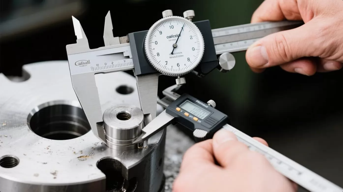
Calipers and micrometers are essential precision instruments for measuring the dimensions of a machined workpiece to ensure it meets specifications. Calipers, available as vernier, dial, or digital types, are versatile for measuring external diameters, internal diameters, and depths, with accuracies typically within 0.001 inches (0.02 mm). They are ideal for quick checks during machining. Micrometers provide higher precision, often to 0.0001 inches (0.002 mm), and are used for critical measurements like outside diameters or thicknesses. To use these tools, ensure they are calibrated, handle them gently to avoid damage, and take multiple measurements at different points to confirm consistency. Clean the workpiece and tool surfaces before measuring to prevent errors from debris or oil.
Evaluating the surface finish of a workpiece is crucial for ensuring it meets functional and aesthetic requirements, such as smoothness for bearing surfaces or grip for knurled parts. Surface finish can be assessed visually or with tools like a surface roughness tester, which measures parameters like Ra (average roughness) in microinches or micrometers. Visually, look for uniform tool marks, absence of scratches, or chatter marks, comparing the surface to a surface finish comparator if available. Factors affecting finish include tool sharpness, feed rate, and cutting speed—lower feed rates and sharp tools typically yield smoother surfaces. If the finish is inadequate, adjust machining parameters or perform a light finishing pass to improve quality.
Tolerance checking ensures the workpiece dimensions fall within the acceptable range specified in the design, critical for parts that must fit or function with others. Tolerances are typically expressed as a plus/minus range (e.g., ±0.005 inches). Use calipers, micrometers, or more precise tools like go/no-go gauges to verify dimensions against the blueprint. Measure multiple points, especially on cylindrical surfaces, to account for potential tapering or out-of-roundness. If a dimension is out of tolerance, assess whether it can be corrected with additional machining or if the workpiece is scrap. Maintaining consistent machining conditions, such as proper tool setup and spindle speed, helps achieve tolerances, and regular calibration of measuring tools ensures reliable results.
Thread cutting on a lathe involves creating helical grooves, known as threads, which can be internal (inside a hole, like a nut) or external (on a cylindrical surface, like a bolt). External threads are cut on the workpiece’s outer diameter using a threading tool that shapes the material as it rotates, requiring precise tool alignment to ensure consistent thread pitch. Internal threads are cut inside a pre-drilled hole using a smaller threading tool or tap, often requiring a boring bar for initial hole preparation. External threading is generally easier to set up and inspect, while internal threading demands careful tool clearance and chip evacuation to avoid binding. Both require accurate spindle speed and feed synchronization to match the thread’s pitch, ensuring functional and precise threads.
Thread cutting requires specialized threading tools and precise calculations to achieve the desired thread specifications. The primary tool is a single-point threading tool, ground to a specific angle (e.g., 60 degrees for Unified or Metric threads) to match the thread profile. For internal threads, a threading tool mounted on a boring bar or a tap may be used. To calculate the thread, determine the pitch (distance between threads, e.g., 1 mm or 20 threads per inch) and the major diameter (outer diameter for external threads, hole diameter for internal). Use the lathe’s lead screw and gearbox to set the feed rate to match the pitch, often guided by the lathe’s threading chart. For example, to cut a 1 mm pitch thread, engage the lead screw to advance the tool 1 mm per workpiece revolution. Accurate calculations and tool setup are critical to avoid mismatched or defective threads.
Achieving precision threading requires careful technique and attention to detail to produce functional and accurate threads. Always align the threading tool precisely using a threading gauge to ensure the correct angle and perpendicularity to the workpiece. Start with shallow cuts (0.005–0.010 inches per pass) to reduce tool stress and improve accuracy, gradually deepening the thread while checking progress with a thread gauge or mating part. Use low spindle speeds (e.g., 50–100 RPM) to maintain control and prevent tool chatter, and apply cutting fluid to lubricate and cool the tool, especially for harder materials. Engage the lathe’s half-nut lever consistently at the same point using a thread dial indicator to ensure the tool follows the same path for each pass. Finally, clean chips frequently to avoid clogging, particularly for internal threads, and verify the final thread with a go/no-go gauge for quality assurance.

Chatter and vibration are common issues in lathe operations, manifesting as unwanted noise or marks on the workpiece, often caused by instability in the setup. These can result from an unbalanced workpiece, loose chuck jaws, or excessive tool overhang. To fix chatter, first ensure the workpiece is securely mounted and balanced, using a dial indicator to check for runout. Tighten all components, including the tool post and tailstock, to eliminate looseness. Reduce the tool’s overhang by repositioning it closer to the tool holder, and lower the spindle speed or feed rate to minimize cutting forces. If chatter persists, inspect the lathe’s bed and ways for wear or misalignment, and consider using a heavier tool or damping techniques, such as adding weight to the workpiece, to stabilize the setup.
Tool wear occurs when the cutting tool’s edge dulls or chips, leading to poor surface finishes, increased cutting forces, and potential workpiece damage. Common causes include excessive cutting speeds, improper feed rates, or machining hard materials without adequate cutting fluid. To address tool wear, inspect the tool regularly for signs of dullness, cratering, or edge chipping, using a magnifying glass if needed. Reduce wear by selecting the correct tool material—for example, carbide for hard materials—and adhering to recommended speeds and feeds for the workpiece material. Apply cutting fluid consistently to dissipate heat and lubricate the tool. If wear is significant, regrind the tool to restore its edge or replace it, and adjust machining parameters to prevent recurrence, ensuring longer tool life.
Dimensional inaccuracy occurs when the machined workpiece deviates from the specified dimensions, often due to improper setup, tool issues, or machine wear. Common causes include misaligned tailstock, incorrect tool height, or thermal expansion of the workpiece. To fix this, verify tool alignment and height using a center gauge or dial indicator, ensuring the tool is at the spindle centerline. Check tailstock alignment with a test bar to prevent tapering. Measure the workpiece frequently with calipers or micrometers during machining to catch deviations early. Compensate for thermal expansion by allowing the workpiece to cool before final measurements. If inaccuracies persist, inspect the lathe’s lead screw and ways for wear, and calibrate the machine to restore precision.
Regular daily and weekly checks are essential to keep a lathe in optimal condition, ensuring safety and precision during operation. Daily, before starting the lathe, inspect for loose components, such as bolts, chuck jaws, or tool post, and tighten as needed. Check lubrication levels in the headstock, carriage, and tailstock, topping up with the manufacturer-recommended oil or grease. Verify the emergency stop functionality and ensure the work area is free of debris. Weekly, perform a deeper inspection, examining belts and gears for wear, checking the spindle bearings for unusual noise, and confirming the alignment of the tailstock and carriage. Document any issues and address them promptly to prevent downtime and maintain the lathe’s long-term reliability.
Maintaining the coolant system is critical for lathes equipped with coolant pumps, as it prolongs tool life and improves surface finish by reducing heat and friction. Daily, check the coolant level in the reservoir and top up with the appropriate coolant type (e.g., water-soluble oil or synthetic fluid) as specified by the manufacturer. Inspect the coolant for contamination, such as metal chips or bacterial growth, which can clog nozzles or degrade performance, and replace it if cloudy or foul-smelling. Weekly, clean the coolant tank and filters to remove sludge, and flush the system periodically to prevent buildup. Ensure the coolant delivery nozzles are unobstructed and properly aimed at the cutting zone to maximize cooling efficiency and prevent corrosion of lathe components.
Cleaning the bed and lead screw is vital to maintain the lathe’s accuracy and smooth operation, as debris or dried coolant can cause wear or binding. After each use, remove metal chips, dust, and coolant residue from the bed’s ways using a soft brush or compressed air, taking care not to scratch the polished surfaces. Wipe the bed with a clean, lint-free cloth dampened with a mild solvent or machine oil to remove stubborn grime, then apply a thin layer of way oil to prevent rust and ensure smooth carriage movement. For the lead screw, used in threading operations, clean it weekly with a brush to remove chips and lubricate it with a light machine oil to reduce friction. Regular cleaning and lubrication of these components prevent premature wear and maintain machining precision.
CNC lathes (Computer Numerical Control) differ significantly from manual lathes in their operation, precision, and capabilities, offering automation for complex machining tasks. Manual lathes rely on operator skill to control the tool path, spindle speed, and feed rate using handwheels and levers, making them suitable for simpler, one-off parts but prone to human error. In contrast, CNC lathes use computer programs to precisely control tool movements and machining parameters, enabling high repeatability and the production of intricate geometries, such as complex curves or threads, with minimal operator intervention. CNC lathes are faster and more efficient for high-volume production but require programming knowledge and higher initial costs, while manual lathes are more accessible for beginners and small-scale projects.
G-code is the programming language used to control CNC lathes, consisting of commands that dictate tool movements, speeds, and operations. Basic G-code commands include G00 for rapid positioning (moving the tool quickly to a location without cutting), G01 for linear interpolation (cutting in a straight line at a specified feed rate), and G02/G03 for circular interpolation (cutting clockwise or counterclockwise arcs). Other essential codes are M03 to start the spindle (clockwise rotation), M05 to stop it, and F to set the feed rate (e.g., F0.01 for 0.01 inches per revolution). Understanding these commands allows operators to create programs for basic operations like turning, facing, or threading. Always verify G-code programs using a simulator to prevent collisions or errors before running them on the lathe.
The programming workflow for a CNC lathe involves several steps to translate a part design into a machined component. Start by creating a CAD drawing (Computer-Aided Design) of the part, specifying dimensions and tolerances. Convert the drawing into a CAM program (Computer-Aided Manufacturing) to generate G-code, defining tool paths, speeds, and feeds based on the workpiece material and tools. Next, input the G-code into the CNC lathe’s control panel or upload it via software. Before machining, perform a dry run or simulation to verify the program, checking for errors like tool collisions or incorrect paths. Set up the workpiece and tools as you would for a manual lathe, then run the program, monitoring the operation for issues. Post-machining, inspect the part with calipers or micrometers to ensure it meets specifications, refining the program if needed for precision and efficiency.

Choosing the right practice materials is crucial for beginners to build confidence and develop lathe skills without risking damage to tools or the machine. Start with soft, machinable materials like aluminum, brass, or mild steel, which are forgiving and easier to cut compared to harder materials like stainless steel. For even safer practice, consider plastic (e.g., Delrin or nylon) or soft wood, which require less cutting force and produce manageable chips. Avoid brittle or abrasive materials early on, as they can accelerate tool wear or cause unpredictable results. Source practice materials in small, round stock (e.g., 1–2 inches in diameter) to simplify chucking and minimize setup time, and always ensure the material is free of defects like cracks to prevent issues during machining.
Engaging in simple project ideas helps beginners apply lathe techniques while creating functional or decorative items, making learning enjoyable and practical. Start with basic projects like turning a cylindrical pen blank, which teaches turning and facing while requiring minimal precision. Progress to a brass mallet head, incorporating knurling for grip and drilling for handle attachment. For a slightly more advanced project, try making a steel bottle stopper, which involves threading and tapering. These projects build skills in tool setup, measuring, and surface finishing while producing tangible results. Choose projects that match your skill level, and always plan the sequence of operations (e.g., facing before turning) to ensure accuracy and safety.
Accessing quality learning resources accelerates skill development and deepens understanding of lathe operations for beginners. Start with online tutorials and video platforms like YouTube, where experienced machinists demonstrate techniques such as tool setup, threading, and safety practices—look for channels by reputable creators or trade schools. Books like “How to Run a Lathe” by South Bend Lathe or “Machinery’s Handbook” provide detailed, authoritative guidance on lathe operations and machining principles. Join online forums or communities, such as Reddit’s r/Machinists or Practical Machinist, to ask questions and share experiences with other hobbyists and professionals. Local community colleges or makerspaces often offer hands-on lathe courses, providing supervised practice and access to equipment. Consistently explore these resources to build a strong foundation in lathe proficiency.
Learning how to operate a lathe may seem daunting at first, but once you understand the fundamentals, it becomes an incredibly rewarding and empowering skill. From shaping raw materials into useful parts to refining your precision and technique, lathe work opens up a world of creativity and craftsmanship.
Whether you're a student, hobbyist, or future machinist, the best way to learn is by doing. Start with soft materials, practice with simple projects, and gradually challenge yourself with complex operations. Mistakes will happen—that's part of the learning process. Just keep at it, and soon you'll be confidently running your lathe like a pro.


Learn how to operate a lathe with this all-in-one beginner’s guide—covering safety, tools, setup, and expert tips. Perfect for DIYers, machinists, and students! Start turning like a pro today.

Discover the top 10 aluminium doors and windows manufacturers in China for 2025, including OPPEIN, Mannlee, and Paiya. Explore their innovative aluminium solutions, from energy-efficient windows to luxury doors, backed by LEADCNC’s advanced production lines.

Discover the unbeatable power of CNC machine centers for aluminum processing. LEADCNC’s Ultra X380 & Emerald F550 deliver 0.1mm precision for doors, windows, and more. Explore types, benefits, and why we dominate!
Rising costs and delays killing your CNC door & window profits? Upgrade to a smart window production line with LEADCNC to survive 2025!


.png)